Boxing up the Speed Vest
The original MAKE article on the Speed Vest was cavalier with respect to the packaging. The authors state that they simply threw the parts into a small soap box. They also mentioned that the electronics kept getting accidentally ripped out and had already needed to be redone three times. It seemed like some improvements were in order, and thus started my biggest mod so far to the original Speed Vest design: adding a project enclosure.
The heart of the Speed Vest is the Arduino Duemilanove board, as shown in an earlier post. A ribbon cable runs from the Arduino to the cloth in the vest. The board is hard-wired to a 9V battery, the EL wire power supply, and the wheel sensor on the bike. Note that last connection. If the original design is taken literally, the Speed Vest is always attached to the bike via the wheel sensor. It is fair to assume that a quick connect was in there, mentioned or not, but if the cyclist forgot to use it damage could result. Presumably an involuntary exit from the bike — falling off, say — would have the same effect.
At first I just bought some spade connectors and left it at that. After a little thought, I realized that there are actually two wheel sensor wires, so the sensible approach would be a connector designed for two wires at once. Even then, though, I wondered how one could prevent any tugs on the electronics. Unless the connector were incredibly loose a sudden jerk could still cause damage. And a very loose connector would not be suitable for biking. Eventually I figured it out, electronics 101: put everything in a project enclosure box. Wires go from devices inside of the box to a pass-through connector that is mounted to the side of the box. The mating connector on the other side allows for continuity to wires outside the box. And if there are any sudden stresses from outside the box, the connectors will separate cleanly. But everything inside the box will be safe.
I know…sounds obvious. This is what happens when you are a beginner. The advantage of figuring it out slowly was that I really appreciated the value of using a project enclosure, because every other option I considered had flaws. And it was good to have this appreciation, because making the project enclosure turned out to be difficult for several reasons:
- The box had to be small enough to fit in a bike jersey pocket. This meant very careful selection and placement of components to fit in the limited space.
- I wanted clear plastic to show off the electronics, which is harder to machine than standard opaque plastics such as ABS.
- I had never done this before.
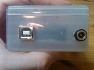
Around this time the catalog from Mouser Electronics arrived. This catalog is over two thousand pages. I went though large sections of it, just flipping through to see what the various options were. Very interesting and tiring at the same time. Eventually I decided to use a panel-mount DC power connector for the wheel sensor wires, and a DPDT push-button snap-mount switch for the main power switch. The Arduino board would sit on nylon spacers with a square hole cut in the box to allow access to its USB input.
I also ordered some fancy project boxes, but when they arrived I realized they weren’t really right; not the ideal size, and space wasted on things I didn’t need, like slots for a PC board. I decided to hang on to them for possible future use, and look for something else. I didn’t feel like waiting another couple of weeks for a special order. I figured I could pick up a plastic box somewhere local. Sure enough, a visit to the Container Store turned up this:
Why would anyone need a clear plastic box to put cream cheese in? I have no idea. But for $2 each I bought a pair to bring home.
For most of the components, a circular hole was good enough. The best way to do it seemed to be the following:
- Make a template of component placement (using software) and tape it to the box
- Mark the center point of each hole with a Sharpie
- Dimple it with an awl
- Drill a pilot hole with the Dremel and a small bit
- Drill a larger hole with the Dremel
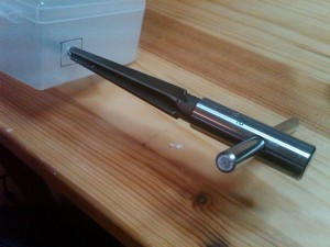
- Use a reamer to enlarge the hole until the component fits in snugly
I rather enjoyed the reamer. I had never used one before. It is a simple and elegant way to get a precisely sized hole.
Because the plastic is soft and can melt, it is important to keep the Dremel speed low. Also, the plastic shavings tended to gunk up the reamer and other tools, and not cleanly separate from the hole. This slowed things down a bit.
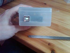
The most difficult component to place was the Arduino board. The USB connector required a square hole, which was a huge challenge. I used the spare box to figure this one out. Square holes are a non-trivial problem and I found a fascinating article with over a dozen way of making square holes in metal. I have a nibbler, and that would have been the best way I think, but the plastic was just a bit too thick. So I ended up drilling a large hole and using a triangular file to enlarge it to the proper size square, test-fitting as I went. This was very slow, but I did get a lovely result.
The Arduino board also needed to be attached with screws and nylon spacers to the bottom of the box. Because the USB opening was going to be the hard part, I did that first and then put the screws and spacers through the board on the inside of the box to figure out where to drill. This worked extremely well.
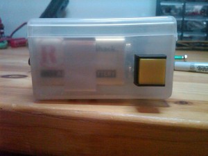
I had greater difficulty with the power switch. I made a template for the placement, but, I managed to mark the pilot hole incorrectly with the awl (I skipped the Sharpie, and didn’t double check before enlarging the hole). Although the misalignment was small, this area was particularly tight on space. So as a result I ended up using a different switch than I had planned, a smaller one, and placed at a slight angle.
I soldered the four leads onto the DPDT switch and then realized…this was a front-mount switch. Oops. So, remove the leads, put the switch in, then solder the leads in with the switch in place. This was extremely difficult and I melted small parts of the box lid in the process.
For the speed sensor passthrough, also a front-mount, I knew enough to solder the wires on with it in place. But I forgot to put the nut on first, so again, I had to redo it.
After that, the only other components were two 9V battery clips, easy enough to mount. For all the parts here, I used screws, nuts, washers, and spacers from the local hardware store. I did not have any lock washers, which could cause a problem down the road in terms of things loosening up. I may order some later and put them in.
One last problem with the switch. It works fine in terms of preventing the battery from draining when it is off. But it did not help with the electroluminescent wire power supply. As I should have realized, that is an AC component, and therefore it puts out an AC voltage even if its leads are not connected to anything. Turning off the vest therefore requires two steps, using the main power switch, and the switch on the EL wire power supply. If the EL wire power supply is not turned off, its battery drains rapidly, as I discovered.
For the ribbon cable, I considered using another panel-mount passthrough. I was actually able to find one for a 14-pin ribbon cable, which wasn’t easy. But in the end I just used the nibbler to cut a slit in the side of the box. It is very unlikely that the vest and the box would be violently separated — they both go on the bike jersey — so strain relief was not as important there.
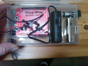
Overall I was happy with the result. I feel the box made the project much more robust, and easier to transport and test. Here is the box, ready for action!
