How to add a power strip to perfboard
Things are moving along well with the automated LED stair light project. All the software is completed and sensors tested. I’ve begun moving the components from breadboard to perfboard, the permanent construction. Along the way I ran into a puzzle that I haven’t seen posted anywhere so I thought I would write about it here.
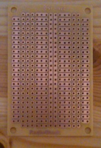
I spent an embarrassingly long time trying to figure out which perfboard to use. A garden variety perfboard has one solder pad per hole. Two additions I wanted were a power strip or power bus as part of the board, and pads designed for an integrated chip (IC) where the pad next to each chip pin was electrically connected. The first option avoids soldering multiple components to one Power In, and the second allows for simpler connection of IC inputs and outputs. An example of a perfboard that has both these options is shown below:
This is a beautiful board, but it was too small for my project. My ICs were also too wide to work exactly with this layout. And my screw terminals at the edge could not make use of the nice connected pads because they themselves are two holes deep. So I hunted around for a larger version of this board and it was surprisingly difficult to find.
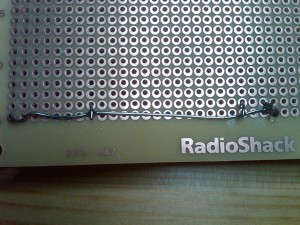
My pad-per-hole perfboard was the right size, so I decided to move ahead with that. And based on an obscure tip in an internet forum, I was able to figure out how to add a power bus to basic perfboard. That is the trick I will show here. It is very simple. Take a piece of solid insulated wire, the same stuff you are using to connect the components, and strip it completely. (You can also use bus wire, but with a decent pair of wire strippers there is no reason to spend extra for a new spool of wire.) Solder it in underneath the perfboard at two points, running along one row or column and there you go — you have a power strip. The only difference is that you must attach components to the wire in addition to or instead of the pads.
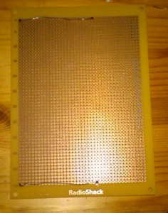
Here is a perfboard with two power strips attached:
Connections are made like this:
Because the power strip is not insulated, it is probably a good idea to cover it with electrical tape once you are finished soldering.
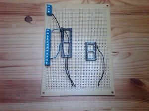
Here is a view from the top. The sockets for the M5451 and the Arduino Mini Pro are visible.

Automated LED stair light circuit starts to take shape. IC sockets and screw terminals are installed and ground wires connected.
This still doesn’t solve the IC connection issue, but one traditional solution is to run the wire in the hole next to the IC pin and bend the lead down to connect with the IC pin. I will be doing that. The other option I’m aware of is to connect adjacent pads with solder, but I have not had good luck heating pads too directly. It’s all too easy to burn them off.
I am planning to complete perfboard soldering today with the exception of the fuse, the fuseholders I ordered were the wrong mount so I need to wait for new ones to arrive.


