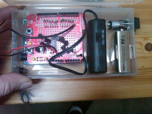
Finishing up the coasterbot electronics (mostly)
After building the Ardweeny, and modifying the servo motors, there was only one major bit of soldering left: the breadboard voltage regulator.
The Ardweeny requires an input voltage of exactly 5V, a common requirement for many chips. This is solved by using a voltage regulator. This is available as a simple component ($1.59 from RadioShack) but for best results you need to add capacitors and so on. Solarbotics makes a nice kit that gives voltage regulation to both sides of a small solderless breadboard, has a switch, and allows for adapter input as well as a battery. This was included as part of the Jameco bundle I started out with.
Putting this one together was pretty straightforward. Some soldering and that was it. The instructions suggest adding the male header pins by seating them in the breadboard first then putting the board on top of them. This was a clever idea that worked well.
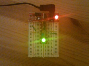
To test, I plugged in an old adapter that was too flaky to be used for its original purpose. The regulator converted it into a steady 5V. Here you see the regulator circuit at the top of the breadboard (in red) and the Ardweeny hooked up to it running vertically, happily blinking green.
The circuit has a serious time constant built into it. Presumably this is to reduce electrical noise. When the power is switched off, it takes several minutes to get down to 3V. Clearly, you don’t want to rely on the regulator switch for fast cutoffs.
This wraps up most of the electronics for the project, other than connecting wires. The H-bridge chip, used to control the servo motors, does not require soldering. The next steps involve working on the robot body, then programming.
Spinning our wheels
We need a way to make the coasterbot move, and without getting too exotic, this means adding some wheels. And some motors to make them turn. The Jameco bundle includes two Hitech HS-322HD servo motors. Once again, this was all new to me, so I did some reading. Servo motors are used to precisely position an output shaft (to which a wheel can be attached). They are very powerful for their size, a useful feature for robots where weight is almost always a concern. They often appear in remote-control devices where precise control of steering is useful.
But. They do not do continuous rotation. There is a mechanical stop built in that will prevent rotation beyond 360 degrees. This is a bit of a problem if we want steady motion in one direction. And the solution is to modify the servomotor.
I have to admit that I was not too thrilled to discover that my motors, ordered as part of a kit made for just this purpose, had to be opened up. Apparently though, these are the best value for the money. I have a pair of DC motors lying around from a beginning robot book project that I never did. I considered using them, but that would have involved making couplers and mounts. Too much work! So on with the servo motor hack.
Fortunately, Karl Demuth did an excellent tutorial on modifying the Hitech HS-322HD. This was extremely helpful and very detailed with lots of photos, so I won’t repeat it here. However, I discovered two things that are worth knowing if you intend to follow those instructions:
- Wear eye protection when snipping off the gear stop. It flies off with a lot of energy, even if you are very gentle.
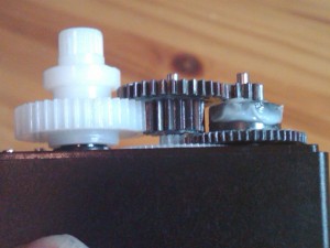
- Once the long screws are removed in step one, the front plate for the gears is also loosened. It can fall off and gears may scatter. This is likely to happen when the potentiometer is removed. For the second motor I ended up having to open up the first one again so that I could reconstruct gear positions. Karl has a nice photo of them from the top; here is the one I needed, a view from the side.
(Karl — if you see this — I couldn’t post a comment on your blog. Please disable the required login feature, most of us don’t have accounts at the other sites listed.)
This went fairly smoothly. Other than the gear scatter, the only annoyance was using the desoldering pump. I found that it works well, but only if you clean it after each suck. This is done either by sticking a pin in it or (every few times) unscrewing the nozzle to clear it out.
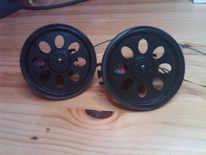
Finally I attached the included wheels, and confirmed that they spin when voltage is applied. They reverse directions when the polarity is switched. Pretty cool.
Ardweeny adventures, part two
I have a working Ardweeny!
The Solarbotics replacement kit arrived this afternoon. I assembled it as before, with a few differences. The male programming headers were put in with the proper orientation. And I decided to test the Ardweeny without soldering the chip in at first — the pressure of the outer pins holds it pretty well.
At first, this looked like a repeat problem; no response when I plugged the Ardweeny into USB power and uploading the sketch failed with the same error. But after I removed the anti-static foam from the chip pins it worked just fine. I know…obvious…I’m new at this.
The Ardweeny does ship with the Blink program burned in. The moment I attached the USB, the LED started blinking.
My old Ardweeny chip, however, is definitely fried. Very glad I didn’t try to rebuild it!
Ardweeny adventures, part one
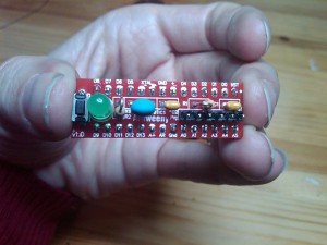
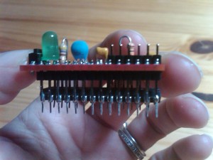
The parts bundle for the coasterbot includes a microcontroller to act as the brain of the robot. It is an Ardweeny, made by Solarbotics. Billed as the “smallest, handiest, bread-board friendly Arduino-compatible”, it literally fits on the back of the ATMega328 chip. It’s a pretty cool design, and incredibly small, as you can see in the pictures below:
The PCB board pins are lightly soldered to the chip pins, then the chip can be placed in a breadboard.
I was able to assemble the kit very easily, soldering the chip in upside down to keep solder off the bottom of its pins. Now to test! The Ardweeny needs a USB-FTDI cable or board in order to load programs onto it. I already had a board with the right form factor labelled “USB to Serial” lying around from an old MachineScience project. Thus I never ordered a new board. Unfortunately, upon closer inspection, I realized the MachineScience board had only 4 pins, while this one has 6. My guess is that there would be some way to get it to work — their functions are certainly similar — but an FTDI board is useful equipment, and not that expensive, so I ordered one and resigned myself to waiting a few days for a programming test.
I thought that I could at least see if I had put the kit together properly. I had heard that the Ardweeny ships with the Blink program already loaded, making the LED turn on and off. So I decided to power it up and see what happened. And there, as we say, my troubles began…
Becuase the Ardweeny is so small, it does not have a voltage regulator. You must give it exactly 5V for it to operate properly. The parts bundle includes a 5V voltage regulator that you can put together. But I already have a fancy powered breadboard that can convert its AC wall power to an exact 5V output. So it seemed reasonable to use it here. I put the Ardweeny in and saw…nothing. I eventually realized that I hadn’t pushed the chip in firmly on the breadboard, and more seriously, I had hooked up the wrong power option and was sending it 9V instead of 5V. The chip is only rated to 6V, so I wasn’t sure if I had fried it or not. I decided to put it aside for now.
The FTDI board arrived a few days later. I installed the drivers on my laptop and attempted to upload the Blink program to the Ardweeny. I got an error message. It seemed that the program was being sent, based on the various blinking lights, but not properly received. I tried various fixes on that computer, and tried another computer as well — which got me a new error message, but no progress.
I noticed that the FTDI board was not fitting very well. I had to apply pressure to keep it in place. It is designed to fit into the the male header pins jutting out from the top of the Ardweeny. (You can see them in front of my index finger in the second photo.) Eventually, I realized that I had soldered in the male headers upside down. The short pins were on top, rather than the long ones, and the long ones are needed to form a solid electrical connection.
This was a rookie mistake. That said, I am going to blame Solarbotics a bit, because in their manual, step 7, they picture the male headers upside down. I naively followed the picture, and that was incorrect.
So my choices were, attempt to unsolder all 28 pins of the chip without damaging it (assuming it wasn’t already fried), and remove it. This would be pretty tough as the chip is already held in place firmly by mechanical pressure alone. Then, I would have to unsolder the header pins and turn them around. All things considered, it seemed better to suck it up and pay $10 for a new kit.
There are only two places to get an Ardweeny: Solarbotics, and Jameco. At first I planned to order from Jameco, because I have used them before and like their order process. But then I saw the Ardweeny from them was $14…? I didn’t want to pay a 40% markup, so went back to Solarbotics, which also seemed to have better prices on some other parts I wanted to bundle with the order. I completed the order smoothly enough, but at the end, I was told that an e-mail receipt couldn’t be sent, yet my order would be placed anyway. Um. I went to the Contact part of the site, and filled in an request for my tracking information. Submitted that, and was told (again) that the e-mail couldn’t be sent.
This was two days ago. I went back to the Solarbotics site and the contact form still doesn’t work. I am going to call and see if the order was actually placed or not, because I am not feeling very confident about it. It is frustrating to always be waiting for parts to arrive. In general you have a choice between waiting two weeks for something or paying an outrageous shipping fee. I should buy stock in FedEx.
The news is not all bad — I have successfully modified one of the servomotors used to turn the wheels and make the robot move. That will be another post.
UPDATE: Solarbotics responded promptly to my phone message, and explained that they were having technical difficulties due to an office move. My order had been placed, and the kit arrived this afternoon.
Constructing the DVD chassis
I was pleasantly surprised to find that my blog of the coasterbot build has been featured in MAKE: Robot Build Dispatch #5. Fortunately I have been working on the bot, so I can add some new material. For this installment I’ll continue discussing the chassis design.
As described in an earlier post, I want to link the DVDs together with the mini-DVDs acting like a swishable tail. I looked into various couplers before going with the “keep it simple” solution: drill holes in the DVDs and screw them together loosely. As shown in the video below, it worked out rather nicely. The tail does swish. It is even posssible to stack the CDs, which looks rather neat, but the addition of wheels and sensors will prevent that in the final design.
If you can’t see the embedded video, here is the direct link.
As far as I can tell, my chassis design is unique. Of course, there may be a reason for this. My robot will lose agility by having multiple segments.
As usual, every time I drill something I tell myself that I need to buy a drill press. The Dremel worked fine for this, but for more precise placement, the slippery CD surface will be an issue. I have the funds, the real question is whether or not I want to expand the workshop into the garage. That would involve moving years of accumulated junk out.
Testing coasterbot construction ideas
The definining feature of a coasterbot is that its chassis relies on CDs or DVDs. Most of the ideas uploaded to the MAKE flickr coasterbot pool have a robot with one CD, or two of them stacked vertically. There is a good reason for this. A small footprint allows for a more agile robot, and the construction is simpler.
But if there is one thing I’m sure of, it’s that I won’t do well in the contest by using a standard design. This is my first robot, so it’s unlikely that it will move better than others, or have a better object avoidance algorithm. I need an original chassis.
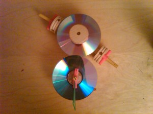
Some folks have figured out how to bend the CDs or melt them into a curved dome. But I haven’t seen anyone use multiple CDs horizontally. I think it might be interesting to chain the CDs together that way. It would allow for any number of additional sensors, one of the contest goals. So, with that in mind, I broke out the Tinkertoys and started putting things together. I started with this:
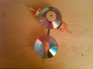 The drive axis orientation is independent of the discs, allowing for them to rotate relative to it. What I really want is for the discs to swing freely relative to each other for a more sinuous motion, but here I was limited by the toolset.
When the kids saw me playing with the Tinkertoys they wanted to help. They pulled out some additional pieces. I thought it might look better if the shaft joining the discs was covered, leading to this:
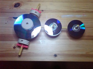
A few days later I thought that it might be fun to treat the second disc as a “tail”. Tails are usually smaller, and longer. Why not put a few mini-DVDs in line? I had to go out and buy the mini-DVDs (which felt slightly wasteful) and have yet another another possibility, shown below. Note that in this case the joining shafts are visible, because the Tinkertoy set did not have a sufficiently small piece.
I like where this is going, but the lack of “swish” in the tail — i.e. rotational freedom — is very clear in this version. I would like the bot to be a little more snake-like. To do that, however, I will need some different couplings. Tinkertoys won’t cut it.
There are risks in making a longer, looser robot. It will not maneuver as quickly, and going into reverse could be interesting. I will have to do some experiments.
Entering the MAKE coasterbot contest
MAKE Magazine has created a contest to make a coaster bot. The basic rules are pretty simple:
Contestants will build “CoasterBots,” mini robot development platforms, made using CD/DVD media as the main body components (“coaster” being slang for a dead/damaged CD/DVD). Your goal is to create a CoasterBot that can navigate a space on its own, avoiding obstacles, and that is designed so that additional sensor systems (proximity, heat, light, sound, etc.) can be added “on top” of this obstacle-avoidance behavior. Contestants are free to use the CD/DVD media in any way they choose. Extra points will be given for creativity and innovation in the overall design.
I have never built a robot before. But I want to.
I have done large parts of “Robot Building for Beginners”. That robot does not have a microcontroller, though, so once I understood the basic concepts — and used many of them for the Speed Vest — I lost interest in building it. So this contest is perfect, challenging and creative, but not (I think) ridiculously hard.
The contest is sponsored by Jameco, who offer a bundle of parts to build the bot. I already had much of the basic hardware, but in the end I decided to go ahead and buy it for the more specialized components, some of which were not available separately at Jameco. It is a nice kit with a few surprising decisions. For example, they provide a spool of black 22 AWG wire, which I think every workshop will have, and various basic screws and nuts. But only two wheels come in the bundle — which won’t be enough for the robot to balance. It will need another wheel or roller.
For the included Ardweeny, there is no USB-to-FTDI cable or board. Without it, you can’t program the Ardweeny. I was fortunate here — I have a leftover board from MachineScience that will do exactly this.
One of the first steps is to design a chassis. Some people have already done some impressive work in this department, bending the CDs with a heat gun or deforming them in an oven. I am having a bit of trouble thinking of something unique to do. One option, there are a ton of unused children’s toys around here. It would be a point of pride to recycle them into a project. And toy parts are pretty!
Speed Vest on the road!
The Speed Vest went for its maiden voyage today. The video below shows me riding it at night outside my house.
If you can’t see the embedded video, here is the direct YouTube link.
For the record, I can bike faster than 6 miles per hour, but we had to work around the limitations of using a phone video camera and a stationary videographer. Also, I do have a rear light on the bike, as required by law and common sense; it was left off for better visuals. The bright stripes that appear elsewhere are due to reflective tape on my jacket, saddle bag, and shoes. I had never seen them in use before and was impressed with their visibility.
I am really pleased with the Speed Vest’s performance and will definitely use it on nighttime rides. I don’t ride after dark very often, but with bling like this I will be motivated.
Finishing touches for the Speed Vest
With the electronics complete, there were only a few steps left to finish the Speed Vest. The digits had been sewn into a large piece of black denim cloth. It was now time to put this in a more attractive shape. After some consideration I decided to go with a trapezoid, as the original authors did. I wanted something that could be used without being attached to a jacket. It’s warm here now, and permanently attaching the Speed Vest to a jacket would limit its usefulness.
Since I don’t own a sewing machine, a friend of mine — Sherri — kindly offered to do the final stitching. But I had to pin the cloth into the proper shape for her. This took a surprisingly long time to do right. I quickly figured out that doing it “by eye” looked pretty awful. A template didn’t work too well either. In the end, I determined the bisecting line, then did precise measurements out from that to each edge. After a lot of pinning and repinning, the vest looked pretty decent:
Another small item, the wires for the wheel sensor needed to be made longer. The input from them goes into the back of a jersey or jacket rather than a computer at the top of the stem. It is a greater distance. So I broke out the heat shrink tubing and went to town. I have a 100′ spool of the stuff lying around — it was such a great deal, I couldn’t resist — and thought this would be a perfect use for it. As it turns out, there is a limit to how far you can push two wires through a single piece of heat shrink tube, but with two pieces of tubing I got the job done nicely. (The ability to extend power cords may be my favorite hacking trick thus far. I feel like the world is at my fingertips.)
The ribbon cable, by contrast, needed to be significantly shortened, so I cut it and crimped on a new connector.
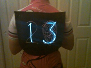
Sherri did a beautiful job sewing, and one day turnaround no less. As a quick test, I attached the vest to a bike jersey and used the wheel sensor magnet to generate a reading:
The only thing left to do is to take the vest out on the bike! I am planning to do this on our next Thursday night ride.
UPDATE: Some people have pointed out that in this photo, the corners seem very sharp. This is due to the very hasty safety pin job I did, it had been a long day and I just wanted to get the picture. The vest is soft and can match the rounding of my shoulders when attached properly.
Boxing up the Speed Vest
The original MAKE article on the Speed Vest was cavalier with respect to the packaging. The authors state that they simply threw the parts into a small soap box. They also mentioned that the electronics kept getting accidentally ripped out and had already needed to be redone three times. It seemed like some improvements were in order, and thus started my biggest mod so far to the original Speed Vest design: adding a project enclosure.
The heart of the Speed Vest is the Arduino Duemilanove board, as shown in an earlier post. A ribbon cable runs from the Arduino to the cloth in the vest. The board is hard-wired to a 9V battery, the EL wire power supply, and the wheel sensor on the bike. Note that last connection. If the original design is taken literally, the Speed Vest is always attached to the bike via the wheel sensor. It is fair to assume that a quick connect was in there, mentioned or not, but if the cyclist forgot to use it damage could result. Presumably an involuntary exit from the bike — falling off, say — would have the same effect.
At first I just bought some spade connectors and left it at that. After a little thought, I realized that there are actually two wheel sensor wires, so the sensible approach would be a connector designed for two wires at once. Even then, though, I wondered how one could prevent any tugs on the electronics. Unless the connector were incredibly loose a sudden jerk could still cause damage. And a very loose connector would not be suitable for biking. Eventually I figured it out, electronics 101: put everything in a project enclosure box. Wires go from devices inside of the box to a pass-through connector that is mounted to the side of the box. The mating connector on the other side allows for continuity to wires outside the box. And if there are any sudden stresses from outside the box, the connectors will separate cleanly. But everything inside the box will be safe.
I know…sounds obvious. This is what happens when you are a beginner. The advantage of figuring it out slowly was that I really appreciated the value of using a project enclosure, because every other option I considered had flaws. And it was good to have this appreciation, because making the project enclosure turned out to be difficult for several reasons:
- The box had to be small enough to fit in a bike jersey pocket. This meant very careful selection and placement of components to fit in the limited space.
- I wanted clear plastic to show off the electronics, which is harder to machine than standard opaque plastics such as ABS.
- I had never done this before.
Around this time the catalog from Mouser Electronics arrived. This catalog is over two thousand pages. I went though large sections of it, just flipping through to see what the various options were. Very interesting and tiring at the same time. Eventually I decided to use a panel-mount DC power connector for the wheel sensor wires, and a DPDT push-button snap-mount switch for the main power switch. The Arduino board would sit on nylon spacers with a square hole cut in the box to allow access to its USB input.
I also ordered some fancy project boxes, but when they arrived I realized they weren’t really right; not the ideal size, and space wasted on things I didn’t need, like slots for a PC board. I decided to hang on to them for possible future use, and look for something else. I didn’t feel like waiting another couple of weeks for a special order. I figured I could pick up a plastic box somewhere local. Sure enough, a visit to the Container Store turned up this:
Why would anyone need a clear plastic box to put cream cheese in? I have no idea. But for $2 each I bought a pair to bring home.
For most of the components, a circular hole was good enough. The best way to do it seemed to be the following:
- Make a template of component placement (using software) and tape it to the box
- Mark the center point of each hole with a Sharpie
- Dimple it with an awl
- Drill a pilot hole with the Dremel and a small bit
- Drill a larger hole with the Dremel
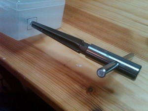
- Use a reamer to enlarge the hole until the component fits in snugly
I rather enjoyed the reamer. I had never used one before. It is a simple and elegant way to get a precisely sized hole.
Because the plastic is soft and can melt, it is important to keep the Dremel speed low. Also, the plastic shavings tended to gunk up the reamer and other tools, and not cleanly separate from the hole. This slowed things down a bit.
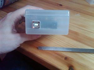
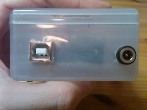
The most difficult component to place was the Arduino board. The USB connector required a square hole, which was a huge challenge. I used the spare box to figure this one out. Square holes are a non-trivial problem and I found a fascinating article with over a dozen way of making square holes in metal. I have a nibbler, and that would have been the best way I think, but the plastic was just a bit too thick. So I ended up drilling a large hole and using a triangular file to enlarge it to the proper size square, test-fitting as I went. This was very slow, but I did get a lovely result.
The Arduino board also needed to be attached with screws and nylon spacers to the bottom of the box. Because the USB opening was going to be the hard part, I did that first and then put the screws and spacers through the board on the inside of the box to figure out where to drill. This worked extremely well.
I had greater difficulty with the power switch. I made a template for the placement, but, I managed to mark the pilot hole incorrectly with the awl (I skipped the Sharpie, and didn’t double check before enlarging the hole). Although the misalignment was small, this area was particularly tight on space. So as a result I ended up using a different switch than I had planned, a smaller one, and placed at a slight angle.
I soldered the four leads onto the DPDT switch and then realized…this was a front-mount switch. Oops. So, remove the leads, put the switch in, then solder the leads in with the switch in place. This was extremely difficult and I melted small parts of the box lid in the process.
For the speed sensor passthrough, also a front-mount, I knew enough to solder the wires on with it in place. But I forgot to put the nut on first, so again, I had to redo it.
After that, the only other components were two 9V battery clips, easy enough to mount. For all the parts here, I used screws, nuts, washers, and spacers from the local hardware store. I did not have any lock washers, which could cause a problem down the road in terms of things loosening up. I may order some later and put them in.
One last problem with the switch. It works fine in terms of preventing the battery from draining when it is off. But it did not help with the electroluminescent wire power supply. As I should have realized, that is an AC component, and therefore it puts out an AC voltage even if its leads are not connected to anything. Turning off the vest therefore requires two steps, using the main power switch, and the switch on the EL wire power supply. If the EL wire power supply is not turned off, its battery drains rapidly, as I discovered.
For the ribbon cable, I considered using another panel-mount passthrough. I was actually able to find one for a 14-pin ribbon cable, which wasn’t easy. But in the end I just used the nibbler to cut a slit in the side of the box. It is very unlikely that the vest and the box would be violently separated — they both go on the bike jersey — so strain relief was not as important there.
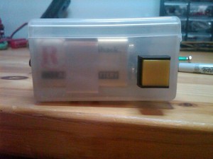
Overall I was happy with the result. I feel the box made the project much more robust, and easier to transport and test. Here is the box, ready for action!
