Playing with the Dremel
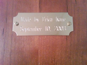
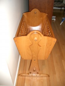
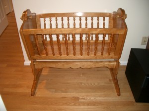
I used my Dremel 4000 for the first time to do a simple project, attaching a brass nameplate to the cherry wood cradle I made back in 2003. I spent many months building the cradle and got it done just in time for Laurel’s birth — we picked it up from the workshop on the way home from the hospital!
 |
 |
I considered doing the engraving myself, but I was able to get an engraved plate from Woodcraft for only $4.99 including shipping. Silly to do it on my own in that case. All that was needed here was to drill some small holes for the screws. I didn’t want the nameplate to be too visible, this is too nice a piece of furniture for that. I decided to put it on the bottom. When my grandchildren inherit it, they will know who made it.
I thought this would be a good opportunity to use the workstation / drill press stand I bought along with the Dremel. After trying it out, however, I have decided to return it. (Fortunately Amazon makes this easy, although I will have to pay the shipping.) The main problem is that it doesn’t fit my model (the numbers are confusing) but it also seems flimsy, no clamps, and hard to put together. I’d rather pay a bit more for a real drill press.
In the end I simply laid the panel on a special mat of rubber balls that I use for woodworking. There was no need for a vise because the piece is very large, and the holes to be drilled very small. I simply held the Dremel in a vertical position. I could have done the job with my DeWalt instead, but the Dremel did have a slightly nicer feel. No use of specialized accessories for this project. The final result:
Speed Vest digits lighting up
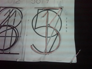
An important part of the Speed Vest project is shaping the electroluminescent wire into digits. The original creators provide a layout template, which has odd digits only on the right, and 0 through 6 on the left. I wanted to do all possible digits on the right, leaving me with only 1 and 2 on the left (I wouldn’t be going over 29 mph unless I was on a steep downhill in any case). With some careful xeroxing, I was able to overlay multiple copies of the template on the right side so that all digits except the number 8 were represented. I wanted to sew on their original odd numbers first, in case the authors were correct in saying that too many layers of EL wire cause problems. This meant 3 layers of paper on the right, which was a little tough to work with, but not impossible.
In the original article, the authors were very enthusiastic about the Buttoneer. It sounds like a wonderful tool: simply load and press, and dual plungers attach a button (or wire) into fabric using a u-shaped fastener. It was available at the same store as the EL wire, so I bought it, along with a refill pack, even though the supplier mentioned that it was only good for thinner wire than what I was using. I thought this would make attaching the wire very fast.
Unfortunately, the Buttoneer is a completely waste of time. I could not even attach the sample buttons after dozens of tries. I finally went to Amazon to see what other people were saying. It turns out the Buttoneer used to be a great tool. Then it was sold to another company, the design was changed, and it is no longer any good. It is possible to get the older version on eBay, but since refills for it are no longer made, it isn’t very useful. This was a big disappointment.
Doing some research, I found that the standard way of attaching EL wire to clothing is to sew it on with monofilament thread. I already had some of this thread, thanks to a glow-in-the-dark solar system kit I had hung on Laurel’s ceiling. It was a bit difficult pushing my smallish sewing needle through the denim cloth, and my first stitches were not very good. Fortunately most digits only required a few stitches, as the cloth tended to hold the wire in place at each end.
After all the digits were put on, the underlying paper template was torn away. On the right side, this was difficult due to the thickness of the paper and the density of overlapping wires. A few stitches were lost due to the strain. Needle nose pliers were helpful in removing the last of the paper.
The end result was very satisfying: all the digits worked and lit up properly. Here is a video. Note that the digits flash in random order; I have not edited the software to put them in order yet.
Saving the TiVo
A couple of weeks ago, I started hearing some funny noises from our Series3 HD TiVo. Sort of like an engine periodically revving up then stopping. I said to my husband, “The cooling fan is going bad.” But we ignored it and eventually the noise went away. Until, a few days ago, the TiVo got stuck at the “Welcome” screen.
The TiVo was extremely hot to the touch. Rather than let it continue to cook, I unplugged it, took it out of the cabinet, and let it cool off. The next morning it was able to boot successfully. But that evening it stopped again and got very hot.
We rely on this appliance a great deal. Nobody in our family watches live TV anymore — we use the TiVo to collect our favorite shows and watch them when we want, without ads. More to the point, we no longer have a stand-alone cable box. The kids particularly used this one, as it is located in the family room (Mommy and Daddy still had access to the one in the bedroom). The Series3 was discontinued in September 2008 and while I don’t remember when we bought it, I am sure it is out of warranty. Replacing it would be at least $400. Since fans are cheap and usually a quick repair, this was an easy call to make.
The first challenge was opening up the box.
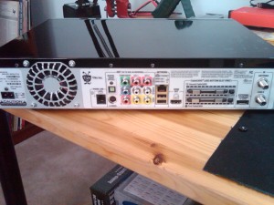
Turns out those screws on the back are a little odd. My Allen keys could sort of turn the screws connected to the fan, but did nothing for the small ones keeping the black top on the box itself. No problem, I figured I would just take the box out to Bruce’s lab, where he has every type of Allen key, then go to Radio Shack and pick up a fan. At the lab, we tried each key, but no luck. We narrowed it down to two keys 1/64″ apart in size; the screws were larger than one and smaller than the other. After belatedly checking online, I discovered that TiVos require you to use a Torx screwdriver. This is a somewhat specialized tool, but I was able to find exactly one set at Home Depot after some hunting by me and a sales associate.
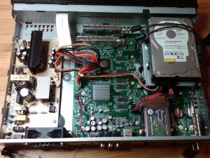
In case you’re curious, this is what the inside of a TiVo looks like. The power supply is on the left, and those large cylindrical capacitors are what you need to avoid when messing around inside. On the upper right is the hard drive. Many people open up their TiVos in order to put in a larger drive.
Now to get a new fan. There are a few standard sizes for computer fans, which is really what the TiVo is. But once again, TiVo used a size that was slightly off — 10mm difference, enough to prevent a drop-in replacement. (There was an odd power connector required too, but I could have spliced it in from the old one.) At this point I knew I was looking at a special order no matter what. Looking up the part number, I found the same (discontinued) fan for $12 at an electronics surplus store. And then paid $20 for expedited shipping.
The fan arrived today, the TiVo is happy, and we are able to watch the Olympics in large-screen HD once again. Life is good.
Replacing an ethernet cable jack
A week ago my 4 year-old daughter bounced on the bed and knocked off my laptop. The laptop was fine, but the ethernet cable had some minor damage. The plastic tab on the RJ-45 plug, which holds it in the computer socket, snapped off. At first, this didn’t seem like a big deal. The cable still worked well. But at random moments it would fall out of the socket and I would lose my internet connection. This got annoying pretty quickly.
Learning how to make an ethernet cable has been on my list for a while. And I didn’t want to lose this particular cable, which is exceptionally long and lets me move the laptop anywhere in the room. (We do have wireless throughout the house, but I like that high-speed.) So I figured I would do a quick and dirty repair and just replace the connector. I picked up 20 of them at Best Buy for $6.99. I didn’t get any other specialized tools, normally an RJ-45 crimping tool is recommended, but I figured my tabletop vise would do as well.
There are many sites that show you how to make an ethernet cable, so I won’t repeat it here. When I made a ribbon cable I was impressed with the elegance and fool-proof nature of the connection. That was not the case here. It is necessary to line up 8 colored wires in the proper order and insert them into the slots of the connector. It is extremely easy for one wire to slide over another as you do this, forcing them into the wrong slots. I crimped my first connector before seeing this error, so I had to cut it off and start all over. Fully straightening each wire and trimming them to exactly the same length is important.
All in all I had to re-insert the wires dozens of times to get them in the right order. I didn’t time it, but total replacement time was 45 minutes to an hour. That is much longer than it should take, and I’m sure a pro would do much better. Compared to the ease of connecting a ribbon cable, though, I was disappointed. It’s amazing that ethernet cables work as often as they do.
There were a few subtleties I learned that were not obvious, so here they are:
- There are two wiring conventions (at least) for ethernet cables. It doesn’t matter which one you use, at least for a straight cable, as long as you are consistent. But if you are only replacing one connector, you will need to use the same convention as on the other end. In my case, it was T568B.
- The wiring diagrams assume you are looking at the connector with the locking tab underneath.
- A short distance into the cable, I discovered a plastic insert running the length of it, dividing the cable into 4 sections. It was too big to fit in the connector, forcing me to strip more of the outer insulation than standard in order to cut it down.
Good news, the cable works. I don’t think I will go into mass production anytime soon though — happy to pay other people to make these for me.
New toys for the workshop
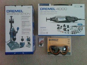
I have some new toys to play with:
The main item is the Dremel 4000. It can drill, sand, plane, shape, rout, basically do everything except bake bread. Initially I’ll be using it to make holes in the enclosure box for the Speed Vest.
I do have another small project in mind. Years ago I made a cradle for our oldest daughter, Laurel. It is made out of cherry wood and took months of work at the local woodworker’s club. Hopefully her children can use it someday too. One thing it doesn’t have is a nameplate. With the Dremel I can engrave one.
WordPress e-mail password recovery
I had quite a scare this morning. I went to add a new blog post, and discovered that I had forgotten my password. GoDaddy insists on stronger password protection than I normally use for sites like this, so I couldn’t remember it. No big deal, there is a nice “Lost password?” link on the page. But when I clicked it, I saw the following:
The e-mail could not be sent.
Possible reason: your host may have disabled the mail() function.
Well. This was not good at all.
Fortunately GoDaddy had a record of the original admin password, and I had never changed it, so I was able to get in. I then added the username/password combo to our secure corporate knowledgebase.
This is not a fool-proof solution, though — it would not necessarily track password updates. I want e-mail password recovery to work! After some searching I found the following post, How to Send Email with WordPress from GoDaddy. After setting up a GoDaddy e-mail account, then downloading and configuring the recommended WP Mail SMTP plug-in, I was able to send a test e-mail.
On our old hosting plan, any e-mail sent to thekanes.org was automatically forwarded to me. In solving this problem I discovered that wasn’t the case. With a little work I configured that option.
Moral of the story: if you install a new app, check that the e-mail password function actually works. You never know when you will need it.
Lighting up the Speed Vest
With the circuit board wired up, the ribbon cable in place, and the electroluminescent wire connected, the Speed Vest was ready for its first end to end test. I used the sample code supplied to have the Arduino run through each of the output pins, lighting up each strand of wire to make sure everything was working properly. I had to modify the code slightly to correspond to my use of different output pins.
One step that made me extremely nervous was connecting the power supply. It provides several hundred volts, and even though the amperage is quite low (and therefore safe), one wants to get the details right. The instructions in the article mentioned red and black wires and where to attach them. Unfortunately, on my power supply they were both black! After a lot of head scratching and playing around with the multimeter, I convinced myself that it was an AC power supply and therefore polarity didn’t matter.
To my gratitude and suprise, the test worked the first time. And in celebration, I posted my first video to YouTube, showing the results. Enjoy!
Learning to use heat-shrink wrap
With the ProtoShield wired up and the ribbon cable prepared, the next step for the Speed Vest was attaching the electroluminescent wires to individual strands of the cable. This was rather fun as it was my first chance to try something I’d been interested in for a while, heat-shrink wrapping.
I paid my Coolight, my EL wire supplier, to solder leads onto the wires for me, as I wasn’t enthusiastic about doing that and EL wire can be a bit fragile. At $3 per strand this was a noticeable addition to the total cost, so other people might want to do it themselves — it didn’t look too difficult. Coolight also added a connector to allow the wire to plug into its power supply. Not only that, but I had ordered just one power supply, since my design only calls for lighting 2 strands at a time. Coolight must have thought I made a mistake, because they went ahead and sent me 12 power supplies without any extra charge. Nice of them.
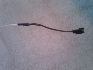
As shipped, the EL wire looked like this:
The connector is on the right, and the pink EL wire is on the left. In order to expose the two wire leads, the first thing I had to do was cut off the connector. As funny as this will sound to an experienced maker, I hesitated. Here I was about to deliberately destroy something that was working! And cutting the wires of an electrical device, no less, which we are all trained to avoid doing as children. But soon enough I took out the wire cutters, snipped off the connectors, and stripped the leads.
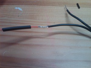
One end of the ribbon cable had no connector, so with some effort one can pull the individual conducting wires away from its neighbors on the side. I stripped off the insulation, slipped a black sleeve of heat-shrink tubing on the wire to the left, and twisted the wires together. Then I applied a thin layer of solder to the metal.
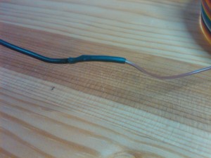
As you can see, this doesn’t look like a very strong joint. Solder will not withstand a great deal of pressure, and the conducting elements are exposed. To fix this, we use the heat-shrink tube. After soldering, the tube was slid from the wire on the left to cover the joint. A hair dryer was used to heat the tube, making it contract to 50% of its diameter and forming a nice seal around the joint as shown below:
This is a simple, cheap method of protecting your work and making it look a lot more professional.
How to make a ribbon cable
If you’ve ever worked around computers, you have seen IDC ribbon cables before. They are extremely common. So when I saw that the SpeedVest required a 14-wire ribbon cable with a 2×7 female header, I figured that I could simply get one at RadioShack or order it online. Turns out, it is not so simple to get exactly what you want pre-made. There are many possible wire combinations, there are many possible headers, and of course the cable can be cut to any length. As a result, the standard method is to buy your own cable, cut it to size, and add the connectors yourself.
(I am sure there are cable companies out there that will make one for you as a special order. But I drew the line at paying for shipping and customization for something that should be very cheap.)
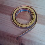
Fortunately, it is very easy to make a ribbon cable. Our goal: turn these
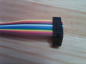
into this
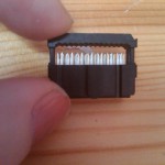
This was my introduction to the wonderful world of crimp connectors. If you think about it, connecting 14 wires securely and easily at both ends sounds like a difficult problem. Take a close look at the photo of the female header. You will see some very sharp pins inside of it. We will place the end of the cable inside there and push, or crimp, those pins through the insulated wires of the ribbon cable. This is done by applying pressure to the black plastic on top. Those pins will form the electrical connection.
If you are using a gray ribbon with red strip to mark the power supply (not relevant here), you will also want to follow the convention of aligning pin 1 of the header with the red strip. It is also to possible to buy fancier headers that enclose a loop of the cable for strain relief.
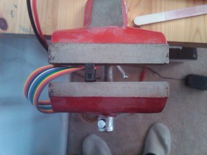
This is a very easy process, but to get good results the pressure must be even. A vise is recommended. Place the end of the cable inside the header. It can go beyond the end a bit, we can always trim later. Start to crimp the connector slightly with your fingers to hold it in place. Then put it in the vise. In this picture we are looking at the vise from the top.
Tighten the vise slowly and evenly until the connector is fully closed. And there you have it….your own cable.
Similar tricks apply for making ethernet cable if you get tired of paying BestBuy $30 for 6 feet of it.
Constructing the Speed Vest circuit board
The electronic circuitry for the Speed Vest is fairly simple. A high-voltage, low ampere power supply lights up strands of electroluminescent (EL) wire. Each wire corresponds to a digit on either the left or right side of the vest. We use a microcontroller, the Arduino Duemilanove, to read input from the wired wheel sensor, calculate the speed, and determine which digit to light up.
The Arduino itself cannot supply enough power to light up the EL wire. For that, we use a power supply provided by Coolight, the makers of the EL wire. The Arduino can output small voltages that are used to control triacs, which are basically fancy transistors. When the Arduino applies the proper voltage to the gate of the triac, the EL power supply connects to the wire and that digit lights up.
This is a picture of the Arduino Duemilanove board I’m using:
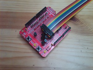
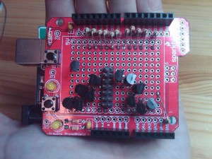
The Arduino is one of the most popular open-source microcontroller boards available, and has a number of add-ons available. There are quite a few circuitboards that plug into the black header pins visible in the upper and bottom right, allowing you to easily add components. For this project we are using the ProtoShield. Here is a picture of it sitting on top of the Arduino board, with the triacs, resistors, and ribbon cable header soldered in:
As you can see from the included hand, this is not very big! Getting all of those triacs in place, and connecting 3 pins from each one to ground, output pin, and ribbon cable header was not easy. Although things look pretty neat on top, the underside is another story. This was the first time I’d soldered in years, and it showed. A few things I learned:
- Use leaded solder. Don’t be environmentally correct and use the lead-free stuff. Not only will you pay a lot more and have to special order it, it doesn’t work. Just go to Radio Shack and pick up a spool of the standard stuff.
- If you have a small space like this, use a sharp conical tip for the soldering iron, not the standard wedge-shaped one. Otherwise you are likely to burn surrounding wires. You can see a few char marks in my work.
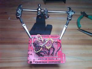
In the original Speed Vest article, the author mentioned simply bending down leads rather than connecting point-to-point with insulated wire. Although I was able to do this for most of the ground connections, it was not possible to do it for the others while keeping the necessary electrical isolation. So I ended up with this:
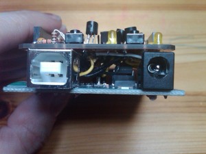
As you can see, darn ugly. It looked somewhat better before I fit the boards together. They need to fit together snugly, so there is not much room for the wires to loop neatly above each other, as they did before. Here is a side view of the Arduino and ProtoShield hooked together — not much room.
I made a few changes to the original Speed Vest schematics. The Arduino has 14 digital output pins. D3, an interrupt, is used by the wheel sensor. I want to make the next version of Speed Vest wireless. My initial research into this suggests that I should reserve pins D0 and D1 as well, as those are used for hardware serial connections. And I am considering adding extra digits to the original design. Fortunately, the Arduino also has 6 analog pins, and they can be used as digital pins too. This allows 12 digits to be powered easily, although this affected the symmetry of my wiring and made it more difficult to place all of the components. Right now I am using the specified 14 pin ribbon cable header — and frankly, I will never unsolder that, reconnecting everything would be too painful — but it would be fairly easy to limit the power supply to one pin instead of two, allowing me to add one more speed digit. That would allow for 0-9 on the right side and 1-3 on the left, as much as I would ever need.
